
From the idea in this post
Yesterday and today I made a proper prototype using blender and godot. Here’s a video demonstrating it:
You encode your object on the surface of a boundary sphere as two textures: a radius texture, and a color texture, both parameterized by the corresponding object surface point’s spherical coordinate angles (ie: uv coordinates correspond to spherical coordinate angles); to get the color at a pixel you do a ray march, transforming each ray point to spherical coordinates, and sampling the radius texture at the angular component of those coordinates
Note that this should be able to accurately encode any model for which there is a single internal point every surface point is visible from without overlap. Despite what I had originally said about this prototype, this (I think) is a superset of all convex objects. Convex objects require every surface point to be visible from every internal point. This requires only that every surface point be visible from one internal point
Here’s an illustration of the two dimensional case:
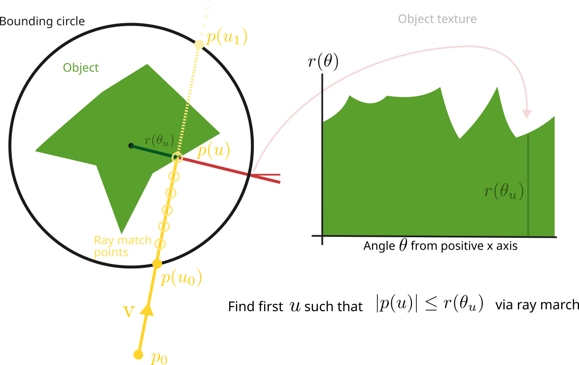
In the 2d case we are projecting a ray from our camera position \$p_0$ into a circle of some fixed radius \$R$ containing an object whose radius (distance from the origin) at each of its surface points is encoded onto the circle (parameterized by angle along the circle), with the goal of finding the first point on the object the ray touches so we can know if the ray hit anything, and where it hit
We do this by finding the \$u$ value where the ray hits the boundary circle, so we know where to start testing points. Then we step along the ray inside the circle until the corresponding encoded radius is greater than that ray point’s radius
As an intuition, instead of picturing stepping inside the circle, picture stepping along the surface of the circle
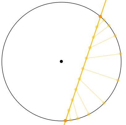
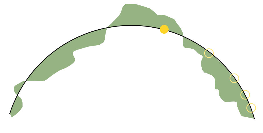
Since the object’s distance from the origin is encoded on the surface of the circle, we are sampling the texture holding these distances at the positions on the surface of the circle corresponding to the points on the ray. We step along the ray inside the circle, get the angle at each of these points - - these angles are the corresponding positions on the surface of the circle - - then we sample the object’s texture at these angles to get the object’s distance at the ray point
A given ray point \$(p_x, p_y)$ angle is:
The three dimensional case is exactly the same except we have two angles
Here is an illustration for the three dimensional case:
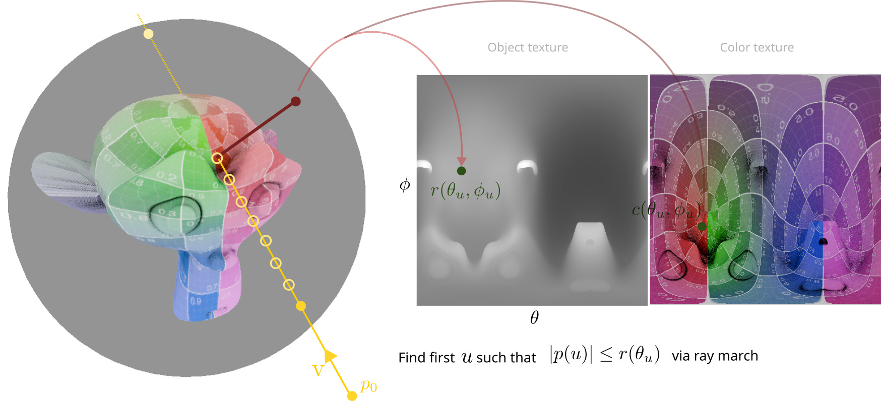
The process is the same:
Find bounding sphere \$u$ values (by solving \$|p_0 + v u|^2 = R^2$ for \$u$; you get two equations corresponding to the entry and exit points on the boundary sphere)
Step along the ray inside the bounding sphere, and for each stepped-to ray point:
Cast the ray point onto the surface of the bounding sphere (where the texture is conceptually encoded) by finding the two spherical coordinate angles (see below)
Sample the object’s radius texture at the ray point’s spherical coordinate angles
If the object radius is greater than the ray point radius, then it’s a hit, otherwise keep stepping
If there was a hit, sample the object’s color texture at that point and use that for the corresponding pixel color, if there was not hit then color that pixel transparent
How to find the coordinate angles (in my formulation I use the xy and horizontal-z angles):
The theta angle is the angle around the vertical axis, and:
The phi angle is the angle from the horizontal plane up and down the vertical axis
Building the textures from a model in blender is actually extraordinarily easy. You just use the following OSL code in blender as a custom lens type, and save the radius and color to two separate files in the compositor. Note it isn’t necessary to do anything with your model past that point because your model is now encoded within the texture files - - that’s the whole point
shader camera(output point position = 0.0,
              output vector direction = 0.0,
              output color throughput = 1.0)
{
    float PI = 3.141592654;
    float PI2 = PI*2;
    point r = camera_shader_raster_position();
    r.x = r.x*PI2;
    r.y = (r.y - 0.5)*PI;
    position = 100*vector(cos(r.x)*cos(r.y), cos(r.y)*sin(r.x), sin(r.y));
    direction = -normalize(position);
}
(Note the 100 multiplier on the position can be anything, just make sure it’s bigger than your model)
Go into a text editor in blender, paste the above code, name the file something (eg: `spherical_camera.osl`), and change your camera object’s type to ‘Custom’ and ‘Internal’ and select the saved file
Center the camera at the center point of your model (corresponds to the center point of the quad that will render it)
Use the following setup in your compositor (or something like this):
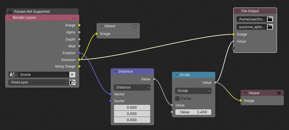
Set the file output location to wherever you want (probably your godot project folder if you’re using godot). Theoretically the ‘Distance’ node’s 2nd argument should be the location of the camera, but I did everything from the origin. The ‘Divide’ node’s 2nd argument should be the radius of your boundary sphere (or something similar; the point is that the largest radius of your model is 1 in your texture for precision purposes, so this node normalizes the radius). Make sure to change file format to ‘Image’ in the ‘File Output’ node’s ‘Node’ settings in the slideout panel on the right (push your N key on your keyboard). Also note I used emissions in my model material so I didn’t have to worry about lighting, but you can use whatever you want. If you use emissions, you have to enable the emissions pass in the view layer panel
Set your render engine to cycles and CPU. Setting it to GPU causes blender to crash for me, and I think I read somewhere that custom lenses don’t work on the GPU or something
In godot, make a new MeshInstance3D, give it a Quad mesh, scroll down to the Geometry section, click to add a material override, add a ShaderMaterial, click it, add a new shader, in the shader editor paste the following:
shader_type spatial;
render_mode blend_mix, depth_draw_opaque, cull_back, diffuse_burley, specular_schlick_ggx;

uniform float radius;

#define PI 3.14159265359
#define TWO_PI 6.28318530718
uniform int MAX_STEPS = 200;

uniform sampler2D radius_texture;
uniform sampler2D color_texture;

varying vec3 world_pos;


vec2 get_spherical_angles(vec3 p) {
  float x = p.x, y = p.y, z = p.z;
  float r_xy = sqrt(x*x + y*y);
  float q = atan(y, x);
  if (q < 0.0) q += TWO_PI;
  float phi = atan(z, r_xy);

  return vec2(q, phi);
}

vec2 angles_to_uv(vec2 qf) {
  float u = qf.x / TWO_PI;
  float v = (qf.y + PI * 0.5) / PI;
  return vec2(u, v);
}

vec2 boundary_sphere_intersection_u(vec3 p0, vec3 v) {
  float vv = dot(v, v);
  float pv = dot(p0, v);
  float pp = dot(p0, p0);
  float R2 = radius*radius;

  float disc = pv*pv - pp*vv + R2*vv;
  if(disc < 0.0)
    return vec2(1.0, 0.0); // no intersection

  float discsqrt = sqrt(disc);
  float u1 = (-pv - discsqrt) / vv;
  float u2 = (-pv + discsqrt) / vv;

  return vec2(max(u1, 0.0), u2);
}


float find_model_intersection(vec3 p0, vec3 v, sampler2D distMap) {
  vec2 interval = boundary_sphere_intersection_u(p0, v);
  if (interval.x >= interval.y) return -1.0;   // no sphere hit

  float startT = interval.x;
  float endT   = interval.y;
  float step   = (endT - startT) / float(MAX_STEPS);

  for (int i = 0; i <= MAX_STEPS; ++i) {
    float u = startT + float(i) * step;
    vec3 p = p0 + v * u;

    // sample encoded distance from texture
    vec2 qf = get_spherical_angles(p);
    vec2 uv = angles_to_uv(qf);
    float encodedDist = radius*texture(distMap, uv).r;

    float sqdist = dot(p, p);

    // inside the shape?
    if (encodedDist * encodedDist >= sqdist) {
      return u;
    }
  }
  return -1.0;
}


void vertex() {
  mat4 billboard_mat = mat4(
      MAIN_CAM_INV_VIEW_MATRIX[0],
      MAIN_CAM_INV_VIEW_MATRIX[1],
      MAIN_CAM_INV_VIEW_MATRIX[2],
      MODEL_MATRIX[3]);
  MODELVIEW_MATRIX = VIEW_MATRIX * billboard_mat;
  MODELVIEW_NORMAL_MATRIX = mat3(MODELVIEW_MATRIX);

  world_pos = (billboard_mat * vec4(VERTEX, 1.0)).xyz;
}


void fragment() {

  vec3 p0 = CAMERA_POSITION_WORLD;
  vec3 v = world_pos - p0;

  float u_hit = find_model_intersection(p0, v, radius_texture);

  if (u_hit < 0.0) { // no hit
    ALBEDO = vec3(0.0, 0.0, 0.0);
    ALPHA = 0.0;
  } else {
    vec3 p_hit = p0 + v * u_hit;

    // sample color texture at the hit point
    vec2 qf = get_spherical_angles(p_hit);
    vec2 uv_hit = angles_to_uv(qf);
    vec4 color = texture(color_texture, uv_hit);

    ALBEDO = color.rgb;
  }
}
I think that’s it. If it doesn’t work just message me or whatever and maybe I can help
Why did I prototype this? Ever since I first saw demos for gaussian splats (and I think even earlier (much earlier) back in the day playing ace of spades aka build and shoot with its weird quasi-voxel surfaces; and come to think of it with the original doom and its billboarded enemies), I’ve had this feeling you could decompose models into fundamental uniform units - - much like gaussian splats or voxels
I had, awhile back, explored neural texture interpolation and implicit textures for use on a quad much like this spherical coordinate based prototype, but ANNs are so incredibly finnicky and expensive I lost interest after awhile
I still think this space has lots of potential interesting ideas in it, so I’ll probably explore more in the future
Work to do with this to make it reasonably viable or determine its viability:
Optimize the stepping algorithm somehow. Probably either using multiple textures, multiple step sizes, or coordinate-informed step sizes
Add depth values so we can overlap multiple of these single-quad models
Develop tooling and workflows for automatically partitioning models into a set of spherically-encoded models
Test and compare performance against regular models in various scenarios (long distance (single quad should probably beat multiple-polys (up to some fixed value) because pixel density is lower), close up, high poly/detail, low poly, etc)
Possibly use an inner sphere entirely contained within model for guaranteed hits to constrain ray marching even further
It would be nice to find a geometry without poles (ie: not this spherical coordinate system). Discontinuities are probably fine to some degree a la uv maps, but prefer to minimize stretching issues.